
What Is Cooling System Engineering and How Does It Work?
Cooling system engineering is the disciplined practice of controlling heat, temperature, airflow, and energy use. It supports buildings, data centers, factories, vehicles, and medical facilities. The work begins with a simple question: where does unwanted heat go?
Engineers study cooling loads, refrigerant behavior, humidity, pressure, airflow, and equipment reliability. They then select components such as compressors, condensers, evaporators, pumps, fans, sensors, and control systems. Each part must cooperate. A small airflow restriction can raise energy consumption and shorten compressor life. A poorly sized unit may cycle frequently, leaving a room damp and uncomfortable.
Willis H. Carrier, widely recognized as a pioneer of modern air conditioning, is often credited with saying, “I applied science to the problem and found the answer.” That idea still defines practical cooling design. Engineers combine calculation with field experience, measurements, and careful testing. A neat diagram can still hide a noisy fan, a blocked filter, or difficult maintenance access.
No design is perfect. Unexpected weather, aging components, changing occupancy, and human error can challenge even a well-planned system. Reliable cooling system engineering therefore includes monitoring, safety margins, preventive maintenance, and honest performance reviews. Engineers must question their assumptions. They should compare predicted efficiency with real operating data, not merely trust software results.
This article explains how cooling systems move heat, regulate indoor conditions, and respond to changing demands. It also considers efficiency, sustainability, controls, and common design weaknesses. The goal is practical understanding, not impressive jargon.
Definition and Scope of Cooling System Engineering
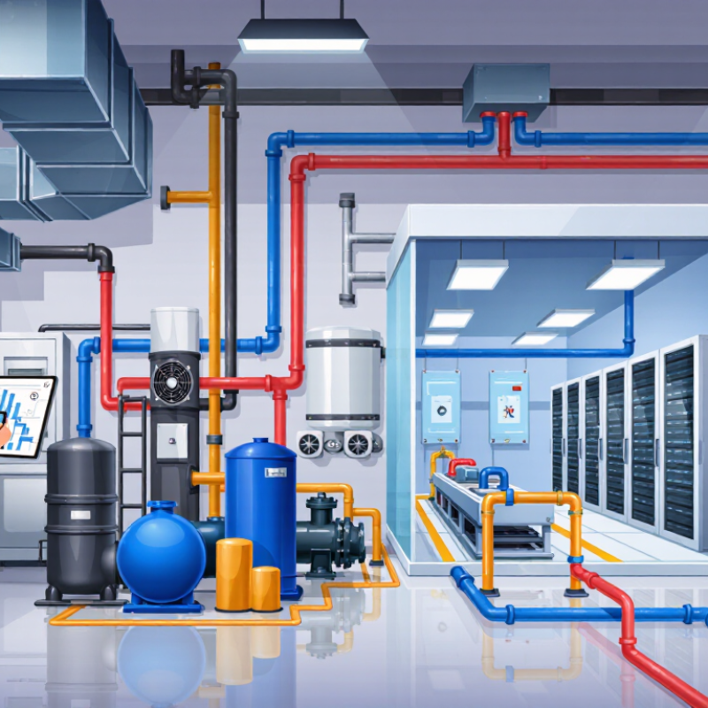
Cooling system engineering is the practical design of systems that remove unwanted heat. It covers cooling equipment, fluid movement, temperature control, and safe heat release. Engineers study how heat travels through air, water, metal, and other materials. Their goal is stable performance, not simply lower temperature.
The scope includes thermal analysis, equipment selection, pipe or duct sizing, sensors, controls, maintenance access, and energy use. Engineers may design cooling for buildings, factories, vehicles, laboratories, or electronic equipment. A typical system moves heat from a warm source to a cooler environment. It may use fans, pumps, heat exchangers, filters, or refrigerant circuits. Field experience matters because dust, vibration, noise, and changing weather affect real performance. A design can appear efficient on paper but struggle when airflow is restricted. That is an important weakness to examine.
Tips: Measure temperatures at several points, not only near the main outlet. Check airflow, fluid pressure, insulation, and filter condition during testing. Leave space for cleaning and repairs. Keep clear records of readings and service dates. Small errors matter. Also, do not trust a single calculation without field verification. Unexpected heat loads often reveal gaps in the original assumptions.
| Engineering Dimension | System Element | How It Works | Typical Data or Range | Engineering Scope and Considerations |
|---|---|---|---|---|
| Definition | Cooling system engineering | The discipline of designing, selecting, integrating, operating, and maintaining systems that remove unwanted heat from equipment, processes, buildings, or living environments. | Heat transfer through conduction, convection, radiation, evaporation, or phase change | Combines thermodynamics, heat transfer, fluid mechanics, controls, materials engineering, and energy management. |
| Primary Objective | Heat removal | Heat flows from a higher-temperature source to a lower-temperature sink through a controlled thermal path. | Cooling capacity commonly expressed in watts, kilowatts, or refrigeration tons | Capacity must match the calculated heat load, including steady-state and transient conditions. |
| Heat Source | Equipment or process load | Electrical power, friction, combustion, chemical reactions, solar radiation, and occupied spaces can generate heat that must be managed. | Load assessment includes sensible and, where applicable, latent heat | Accurate load estimation prevents insufficient cooling, excessive capital cost, and inefficient operation. |
| Heat Transfer Path | Thermal interface and heat exchanger | Heat passes through a conductive interface and is transferred to air, water, refrigerant, or another cooling medium. | Performance affected by thermal resistance, surface area, temperature difference, and flow rate | Designers evaluate contact resistance, fouling, material compatibility, pressure drop, and maintenance access. |
| Cooling Medium | Air, water, glycol solution, or refrigerant | The medium absorbs heat and transports it away from the protected component or space. | Properties include specific heat, density, viscosity, thermal conductivity, and boiling point | Medium selection depends on temperature range, safety, environmental requirements, corrosion risk, and operating cost. |
| Air-Cooled Method | Fan, duct, fin, or air-side heat exchanger | Fans move air across heated surfaces, allowing convection to carry heat to the surrounding environment. | Suitable where ambient air can accept the required heat load | Design must account for airflow distribution, fan power, noise, dust, ambient temperature, and available space. |
| Liquid-Cooled Method | Pump, cold plate, radiator, or liquid heat exchanger | A circulating liquid absorbs heat at the source and releases it through a radiator, cooler, or secondary heat exchanger. | Higher heat capacity and heat-transfer coefficient than air in many applications | Engineers manage flow rate, pressure drop, leakage prevention, water quality, corrosion, and freeze protection. |
| Refrigeration Cycle | Compressor, condenser, expansion device, and evaporator | A refrigerant absorbs heat during evaporation at low pressure and rejects heat during condensation at higher pressure. | Coefficient of performance depends on evaporating and condensing temperatures | System design includes refrigerant selection, pressure control, efficiency, safety, serviceability, and environmental impact. |
| Heat Rejection | Radiator, condenser, cooling tower, or dry cooler | Collected heat is transferred to outdoor air, water, ground, or another external heat sink. | Heat rejection capacity must exceed the useful cooling load plus system losses | Ambient conditions, approach temperature, humidity, water consumption, and seasonal performance influence sizing. |
| Control System | Temperature sensor, controller, valve, and variable-speed drive | Sensors measure operating conditions and adjust fans, pumps, compressors, dampers, or valves to maintain set points. | Control variables may include temperature, pressure, flow, humidity, and differential pressure | Good control reduces energy use, limits thermal cycling, improves stability, and supports fault detection. |
| Energy Performance | Efficiency and power consumption | The system uses electrical or mechanical energy to move heat and operate pumps, fans, compressors, and controls. | Common indicators include COP, EER, seasonal efficiency, and specific energy consumption | Efficiency improves through proper sizing, clean heat-transfer surfaces, optimized controls, insulation, and part-load operation. |
| Thermal Management | Temperature uniformity and hot-spot control | Heat is distributed and removed so that no component exceeds its allowable operating temperature. | Design targets are defined by component limits, process requirements, and safety margins | Engineers analyze thermal gradients, local hot spots, transient loads, airflow paths, and interface materials. |
| Reliability | Redundancy, protection, and maintenance | Backup capacity, alarms, protective controls, and planned maintenance reduce the risk of thermal failure. | Reliability requirements vary by application criticality and allowable downtime | Important measures include filtration, leak detection, overload protection, emergency shutdown, and component access. |
| Safety and Compliance | Pressure, electrical, chemical, and environmental safety | Cooling systems are designed to contain pressure, prevent exposure to hazardous substances, and operate within defined limits. | Requirements depend on system type, working fluid, installation environment, and local regulations | Risk assessment covers electrical isolation, refrigerant handling, water treatment, fire safety, noise, and emissions. |
| Applications | Buildings, manufacturing, transport, electronics, energy, and process industries | The same principles are adapted to different heat loads, temperature ranges, space constraints, and operating profiles. | Applications range from localized component cooling to large-scale industrial heat rejection | System architecture is selected according to capacity, precision, availability, lifecycle cost, and environmental conditions. |
Related Posts
-
China Top 10 Cooling System Suppliers for Reliable Quality?
-
2026 Best Advanced Cooling Systems for Global Buyers
-
Top 10 Efficient Cooling Methods for Businesses?
-
What Is the Best Cooling System Innovation in China?
-
China Top 10 Cooling System Integration Companies?
-
China Top Cooling System Manufacturers Are They Reliable?